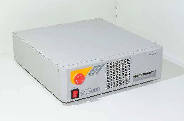
Sankyo SC3000 robot controller
- Manufacturer:

Sankyo Robotics - Model:
Sankyo SC3000 robot controller - Dimension:
530 x 435 x 128 mm - Weight:
11760 g - Availability: Out of Stock
- Condition: Used
-
Price Including VAT: 878,50€
- Ex Tax: 700€
Sankyo SC3000 Robot Controller.
Information regarding Sankyo robots and their controlling (information comes from 5W Tampere's Hacklab):
Connection:
- SCARA robot requires a robot arm to work, control box and also a PC which is connected into controller box serial port (ADS -connector. ADS is located in controllers front panel (DB-9F connector). There are two cables going to robot at the back of the controller, cable with DB-25M-DB-25M connectors for sensor data, and second cable for controlling servo motors.
- In addition power cable, and also crossover serial cable from the front panel's DB-9F connector (ADS) to the control PC's serial port. Front panel DB-25F connector (Pendant) is to be attached to the connector which has magical jumper wires. If the controller does not recognize the correct jumps in pendant connector, servos do not get control.
- Back panel has two RS232-serial port connectors. With own softwares one must use the upper one, which is #8 in robot's software. Front panel serial port is only for controlling the controller, it cannot be accessed from own software.
Startup:
- Make sure that emergency-stop is not depressed, and start the controller from power button. In case all is well Power- and Error lights will light up. ~After half minute the Error light should turn off, and Manip-power ligh up. When servos power will engage a clear audiable click is heard from the relays and from this point on a clear sound is heard from the servos, when they try to maintain their position.
Calibration:
- If front panel Error light flashes in series of four flashes when starting, it means, that device has lost robot arm position data, and zero point and it requires to get the the zero point again. The following procedure is done as follows:
- Turn on the controlling device and open from controlling PC "3000SPWin" software. Select "Maintenance for user" point, and "ABS homing" button after that.
- Follow the instructions on the screen, robot should begin moving, and obtaining zero point for each axis. After each operation the next start of operation must be acknowledged from "ok" button.
- When calibration software tells to shut down "Servo power" voltages, disconnect the connector from the controller's front panel's "Pendant" connector. When the software tells to put the "Servo power" voltages back on, then connect the pendant connector back to it's relevant place.
- When calibration software tells that it is ready, turn off the controller power, and turn them back on. After this error ligt should not flash any more (at least not because of the same reason).
- If "ABS Homing" button is displayed as gray and you cant click it, it is most likely that the serial port is reserved by some other software. If you get error messages at the beginning of the calibration, then the configuration of the robot is incorrectly selected. Try selections "1 unit", "4 axis", "9600 baud". Check that the COM-port is certainly right.
Buzz 2.0:
- With the help of Buzz new tasks can be written, compiled and uploaded them into robot for execution. Programming language is SSL-E, which is resembling C-derived language which is used with Arduino. Programming technical atributes are limited, but on the other hand language offers plenty of ready functions for controlling the robot (SSL-E comprehensive documentation).
- The actual programs are uploaded to the robot with the use of Buzz-software. There can be found in a very comprehensive documentation for this program from a link bellow at the end of the page.
- SC300 can control multiple robots + other actuators in parallel, and because of this reason the structure of the program is not fully trivial. In a simplest case robot needs jobdef.cfg, which has listed all the tasks which are run in controller and other parameters relating to them, and also system task, which id is always 255. In practice it is required to have own task for the robot (usually id == 1), because in system task it is not possible to move the robot, because it is meant only for higher level of task control (for example assembly automation cell). This is archieved quite simply, since every task has a certain bit in address space, which allow to shutdown, start up and othervice control them (check system I/O from documentation)
- When all stuff is uploaded into robot, there should be atleast five files: jobcfg, robot task source code (SSL) and compiled binary (TSK), system task source code (SSL) and compiled binary of that (TSK). In addition to binaries Buzz saves source codes into robot, which results that source codes are always stored. By our knovledge source codes are not used for any purpose in robot. Robot is only interested in .TSK-files, but it is not possible to prevent source code uploading. If desired thay can be removed from robot with filemanager.
- Based on experience it seems like that system task is not starting automatically in boot (some magic bit is needed somwhere?). When own software is happily uploaded into robot, stays system task and robot task as idle. Most likely system can be configured in such manner, that first starts system task and then it starts robot task. So far however we dont master this. Easiest way of starting your own task is to go to software pendant (in Buzz tool bar's right side), select "local" from tabs and right task (most likely "Robot task 2"). Now Start button should be visible under selected task, which will start your own task. When you manage to start your task once, the run bit is switced on in robot controller and the task will start always when the controller is started.
Restrictions:
- SCARA is meant for assembly , so it's instruction set does not support continuous movements. In other words tool stops always in between of every different movement command. Robot supports the specific pick-and-place commands, which allows for smooth path of movement, but for example it will not work as a 3D-printer.
Dimensions:
- Smaller SCARA is by model 8408. The lengths of arms are 300mm and 250mm. which maximum reach is 550mm, Z-axis moves between 0...150mm (increases downwards). XY-plane origo is in a center of main joint. Watching from connector panel X grows to the right and Y forward. Tool minimum distance from main joint is 200mm.
Downloadable files:
Download Sankyo Robotics Buzz 2 application development user guide
Download Sankyo Robotics Buzz 2 user manual
Download Sankyo Robotics SC3000 series controller installation and specification manual
Download Sankyo Robotics SC3000 series controller SSL-E language reference manual
Download Sankyo Robotics Scaran hardware manual
Download Sankyo Robotics SSL-E language reference manual
Download Sankyo Robotics 3000SPWin software maintenance manual
Download Sankyo Robotics 3000SPWin software user manual
Download Sankyo Robotics Scara driver, Buzz V2, and 3000SPWin softwares


